Total time: about 30 minutes · Difficulty: Medium · Cost: ≈ 25-30 €
Why temperature control matters
In a reef tank, thermal stability is just as critical as salinity. A swing of just a few degrees stresses corals and fish, promoting disease and bleaching. During summer, with ambient temperatures above 30°C (86°F), your tank can overheat quickly — especially under LED or metal halide lighting.
The simplest and most effective solution is a cooling fan that turns on automatically when the temperature exceeds a set threshold and turns off once it’s back under control.
With JoyReef, you can build this system for a few euros and monitor it from your smartphone.
What is the JoyReef controller
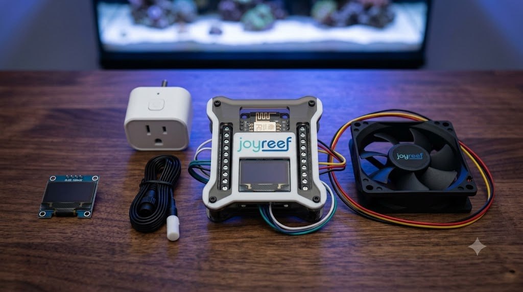
If you already read the ATO guide, you know the drill: a small NodeMCU (ESP8266) that reads sensors (temperature, float switches, pH, ORP) and controls external devices (smart plugs) through the JoyReef portal (portal.joy-reef.com).
In this guide we’ll use the same controller, but instead of float switches we’ll connect a DS18B20 temperature probe and use it to turn a fan on/off via a smart plug.
Parts list — Base setup (≈ 25-30 €)
| Component | Purpose | Estimated cost |
|---|---|---|
| NodeMCU v3 (ESP8266) board | Reads probe and controls plug | 4-7 € |
| DS18B20 temperature sensor with plastic cap | Measures tank or sump temperature | 3-5 € |
| Tasmota smart plug (or Kamoer KXF) | Turns the fan on/off | 12-18 € |
| Aquarium fan / PC fan 12V | Cools the water surface | 5-10 € |
| USB cable for fan power (optional) | Powers the fan if 5V | 2-3 € |
| 4.7 kΩ resistor (pull-up) | Required for DS18B20 1-Wire bus | 0.05 € (included in kits) |
NodeMCU pin map
The JoyReef firmware uses these NodeMCU pins. On the screw shield board, the same names are printed next to each terminal:
| NodeMCU pin | GPIO | Connect |
|---|---|---|
| 3V3 | — | Sensor power (+3.3V) — goes to all sensors |
| GND | — | Ground (return) — goes to all sensors |
| D5 | GPIO14 | DS18B20 probe (yellow data wire) + 4.7kΩ pull-up resistor |
| D3 | GPIO0 | OLED display — SDA (data) |
| D4 | GPIO2 | OLED display — SCL (clock) |
💡 On the shield: pins are labelled with the same names (D5, D3, 3V3…). You don’t need to know the physical pin location — just find the name on the terminal block.
Wiring the DS18B20 probe
The DS18B20 has three wires — do not swap red and black, as this will overheat and damage the sensor:
| Probe wire | Colour | NodeMCU terminal |
|---|---|---|
| VCC (power) | 🔴 Red | 3V3 |
| GND (ground) | ⚫ Black | GND |
| DATA | 🟡 Yellow | D5 (GPIO14) |
- Strip about 5 mm of insulation from each wire (use wire strippers or scissors).
- Insert the bare copper into the hole above the matching terminal: Red → 3V3, Black → GND, Yellow → D5.
- Tighten the screw until the wire no longer slips out when gently pulled. Do not overtighten.
4.7 kΩ pull-up resistor (mandatory!)
The 4.7 kΩ resistor is required for the DS18B20 1-Wire bus to function. Without it, the firmware cannot detect the probe and the temperature will read 0°C or —127°C.
- Connect one leg of the resistor to the 3V3 terminal (together with the probe’s red wire).
- Connect the other leg to the D5 terminal (together with the probe’s yellow wire).
💡 If you have a DS18B20 on a breakout board, the resistor is often already soldered on the PCB. In that case you don’t need to add one.
Fan and smart plug wiring
The fan is not wired directly to the NodeMCU — the controller communicates with the smart plug over Wi-Fi, and the plug supplies power to the fan:
- Smart plug → Fan: plug the fan cable into the Tasmota/Kamoer smart plug.
- Smart plug → Wall: the smart plug goes into a 220V wall outlet.
- Fan power: if your fan is 12V, the smart plug outputs 220V → you need an intermediate 220V→12V power supply, or use a 220V fan, or a 12V PC fan with a dedicated power supply switched by the smart plug.
- Controller → Plug: no cable. The NodeMCU controls the plug over Wi-Fi through the JoyReef portal.
💡 Tip: position the fan to blow across the water surface — forced evaporation is the most effective cooling method.
Final checklist
- All wires securely tightened in the terminals — no exposed copper touching other terminals.
- 4.7 kΩ resistor firmly between 3V3 and D5.
- DS18B20: Red → 3V3, Black → GND, Yellow → D5. Double-check — swapping red/black damages the probe.
- Fan plugged into the smart plug, smart plug plugged into the wall.
- NodeMCU correctly seated on the screw shield, no bent pins.
✅ Wiring complete! Now you’re ready for Part 2: firmware flash, WiFi setup, and probe configuration on the portal.
Where to buy
| Component | Amazon | AliExpress |
|---|---|---|
| DS18B20 | — | AliExpress |
| Tasmota smart plug | — | AliExpress |
| 12V fan | Amazon | AliExpress |
| JoyReef controller | JoyReef Shop | |
👉 Next part: Part 2 — Configure the DS18B20 probe and smart plug on the portal
JoyReef Guide · Part 1 of 3 · v1.0 · Questions? Write to supporto@joy-reef.com