Attention: the modification of electronic devices requires an electronic knowledge and basic safety standards, what reported in this article is for illustration purpose only, we are not responsible for any damage to people or goods caused by misuse or tampering of electric devices.
In the article about T5 we discussed the main limits of this technology, in particular the artificial-looking light they emit. The best way to get rid of this problem is to apply leds that provide beautiful reflection, especially royal blue leds which have wavelength between 445-460 nm.
Today we see how to upgrading T5 fixture with leds: this project was born with the purpose of preserving both architecture and aesthetics, furthermore all the modifications are easily reversible, without leaving any trace, so it is possible to come back to factory configuration.
The intervention has been performed on a ATI sunpower 8×54 watt, a good-quality product, which best feature is the extremely simple construction, that allows easy modification.
The more difficult part of the whole project is the manifacture of a bar capable of replace a T5, exploiting the same connections. We have choose a 10×15 mm, U-shape aluminum bar, enough for dissipating the heat produced by leds. Then, using a precision lathe, we build Delrin (POM) heads for adapting T5 connection (16 mm) to the bar (25 mm). In the pictures you can see the phases of construction and a scale prototype.
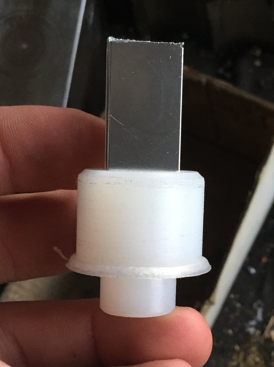
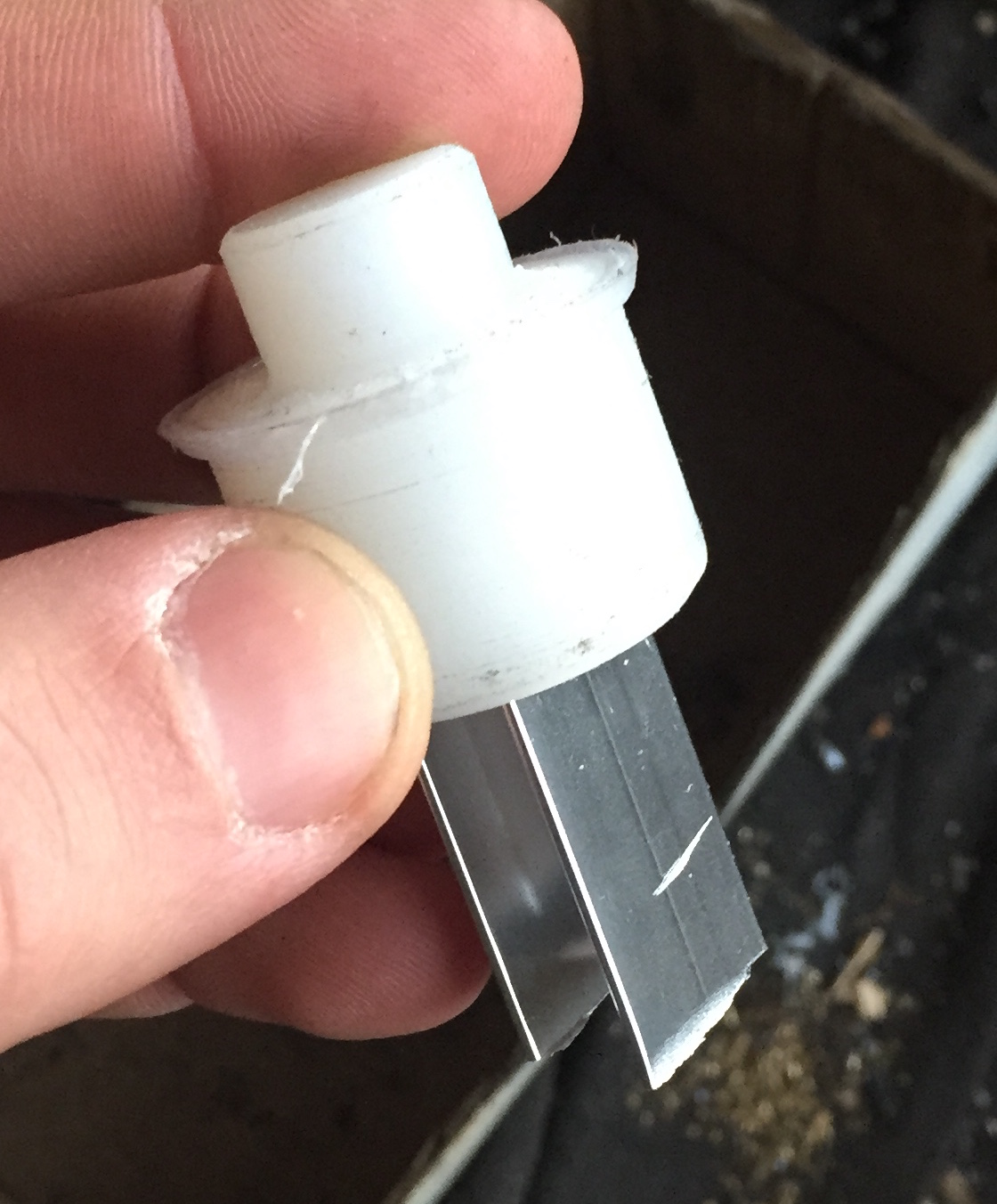
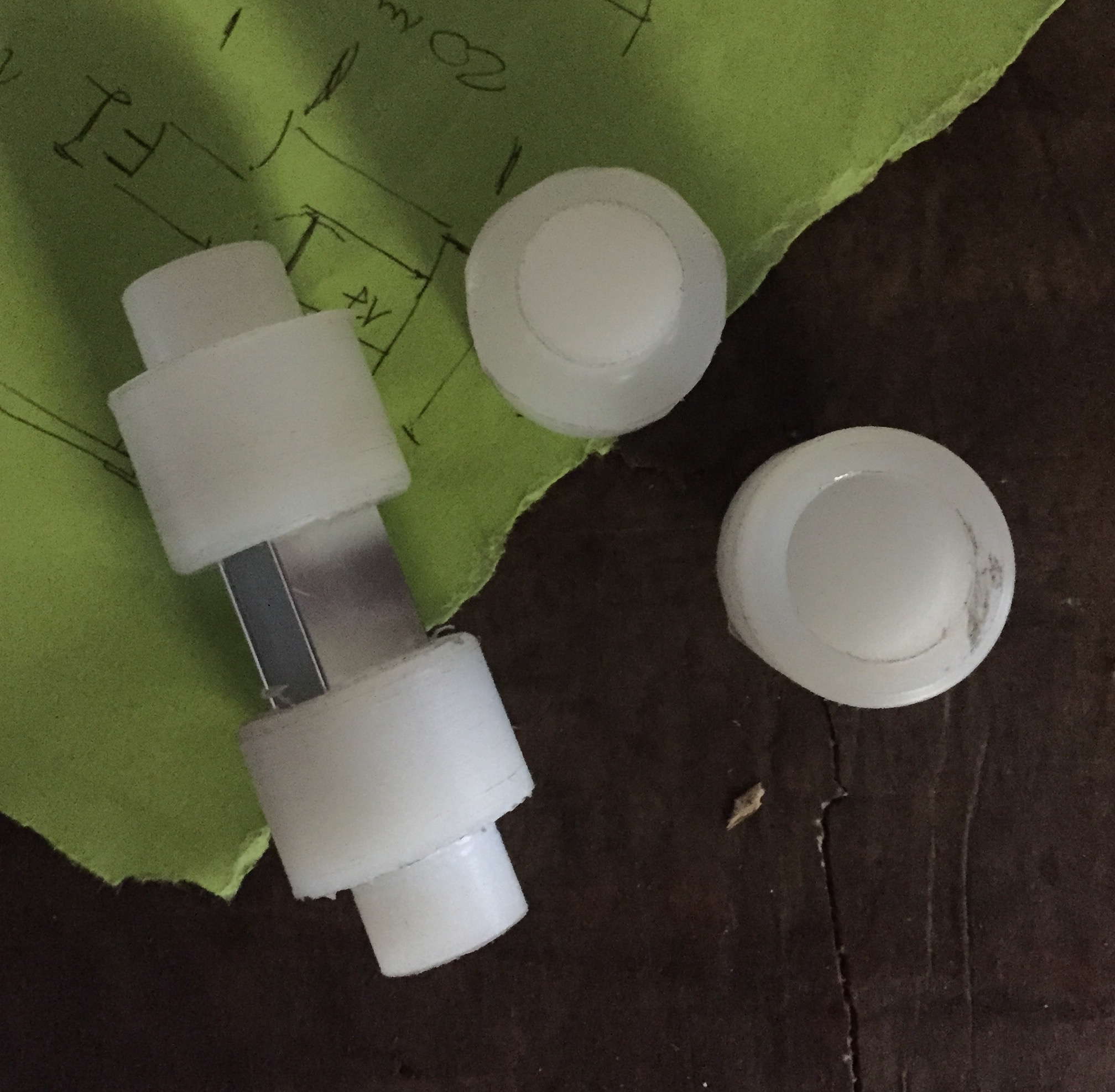
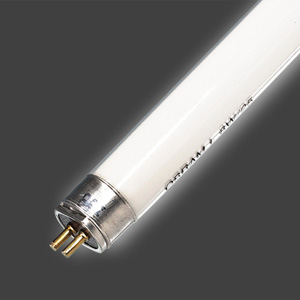
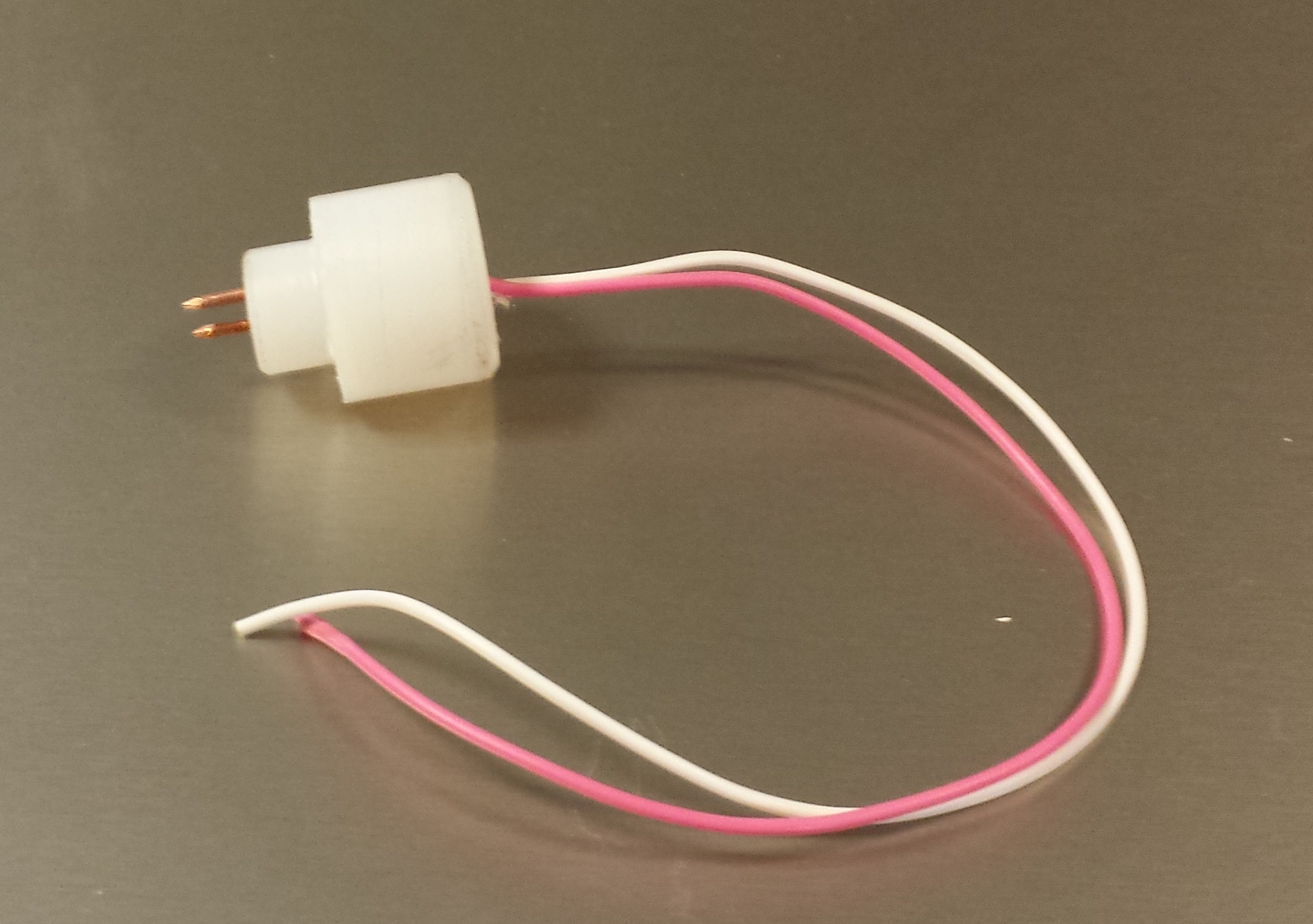
Obviously most people cannot realize such heads, so a good and cheap alternative is to get connectors directly from exhausted tubes, paying attention to glass chippings. Those connectors are ready to use since have their contact pins, while delrin heads need to be reworked for adding contacts. In the picture below you can se a complete head and a T5 connector.
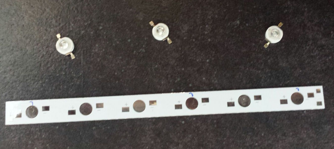
About leds we decided to use cheap products, since their role is only to create a reflection effect and provide actinic light for sunrise and sunset simulation. We bought 3 watt Satisled brand leds with 6 place pcbs, useful to simplify cabling. Here a pictures of led and pcb.
Now let’s see the modification of the fixture, it requires little working time. I try to describe the passages as particularly as possible for facilitating comprehension:
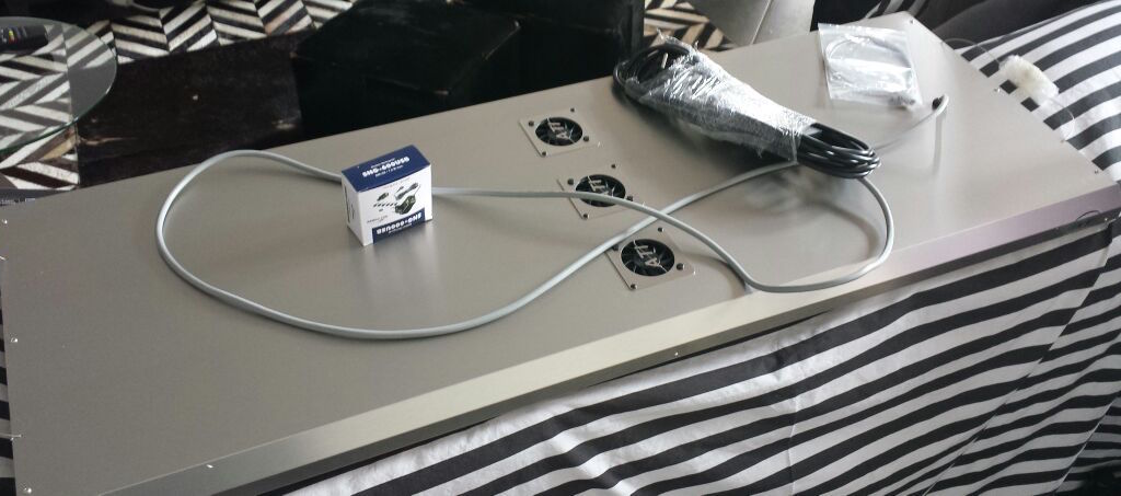
1- Place the fixture on a working table, possibly covered with a sheet for minimizing the risk of scratches. Remove the protection glass and tubes, then disassemble chassis components: 2 sides, 1 support for tubes and electronics, 1 cover with fans. During the disassembly pay attention to power cord, usually it must be removed for separating the cover from electronics support. When finished you should see ballasts.
2- Proceed to identify the tubes you want to replace with leds (we decided to remove tubes 3 and 6) then remove the related reflectors. Follow the cables till the ballast, disconnect and remove it. I point that each ballast has 3 input cables (phase, neutral, ground) and 4 output cables for each tube but usually 1 ballast operates 2 tubes, so the output cables are 6 or 8 depending on manufacturer. A further complication is that probably the 2 tubes you remove are not operated by the same ballast: you have to modify the cabling so that the remaining tubes are all powered up, you can find a wiring diagram directly on the ballast.
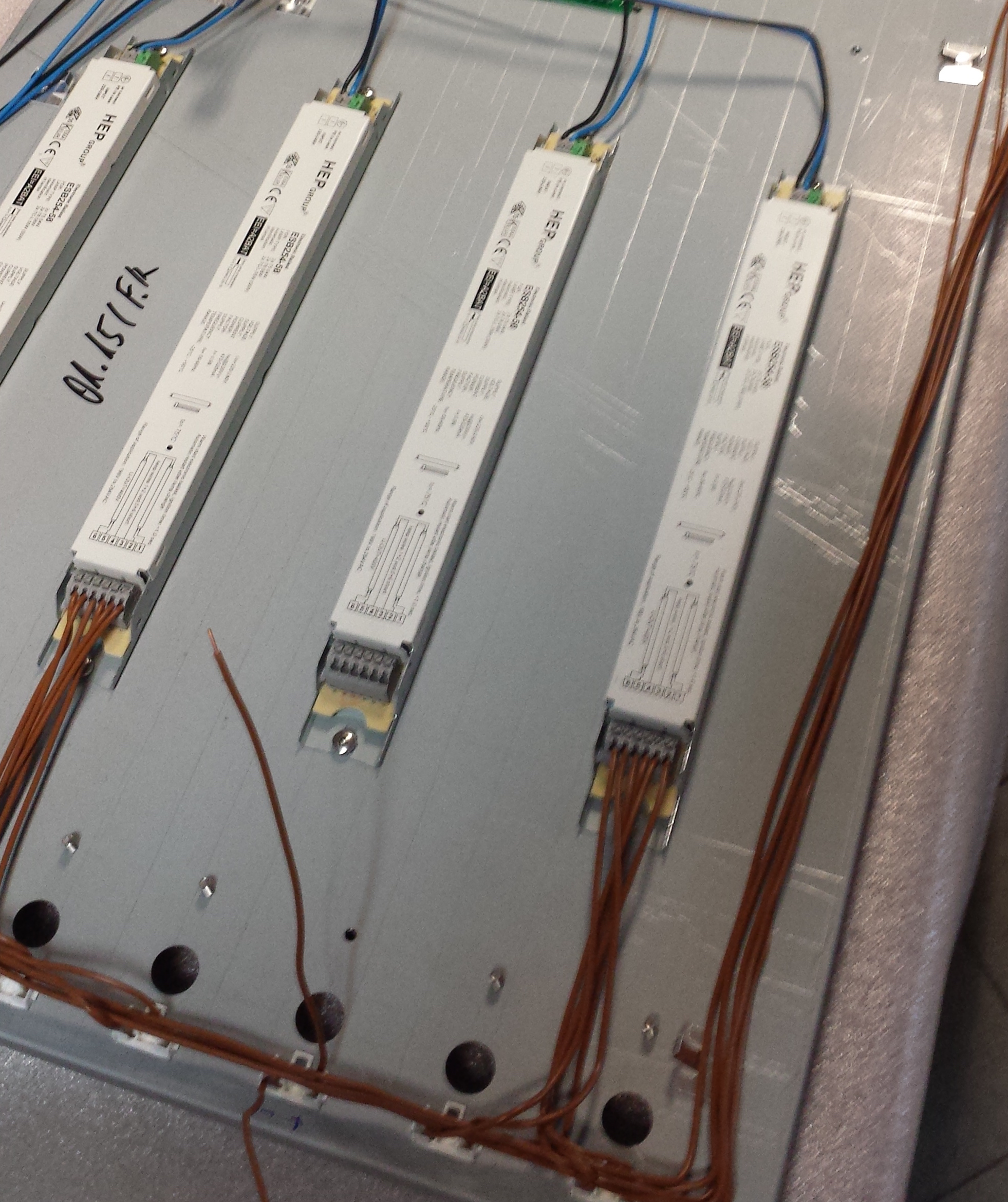
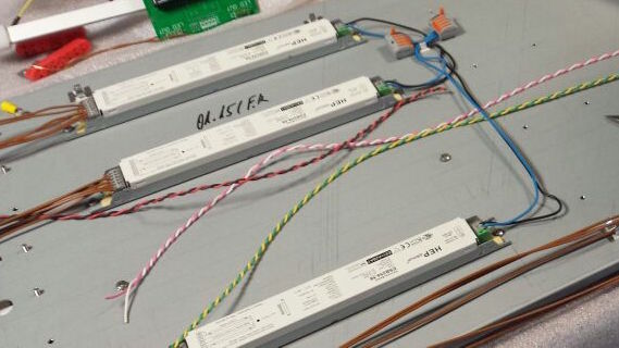
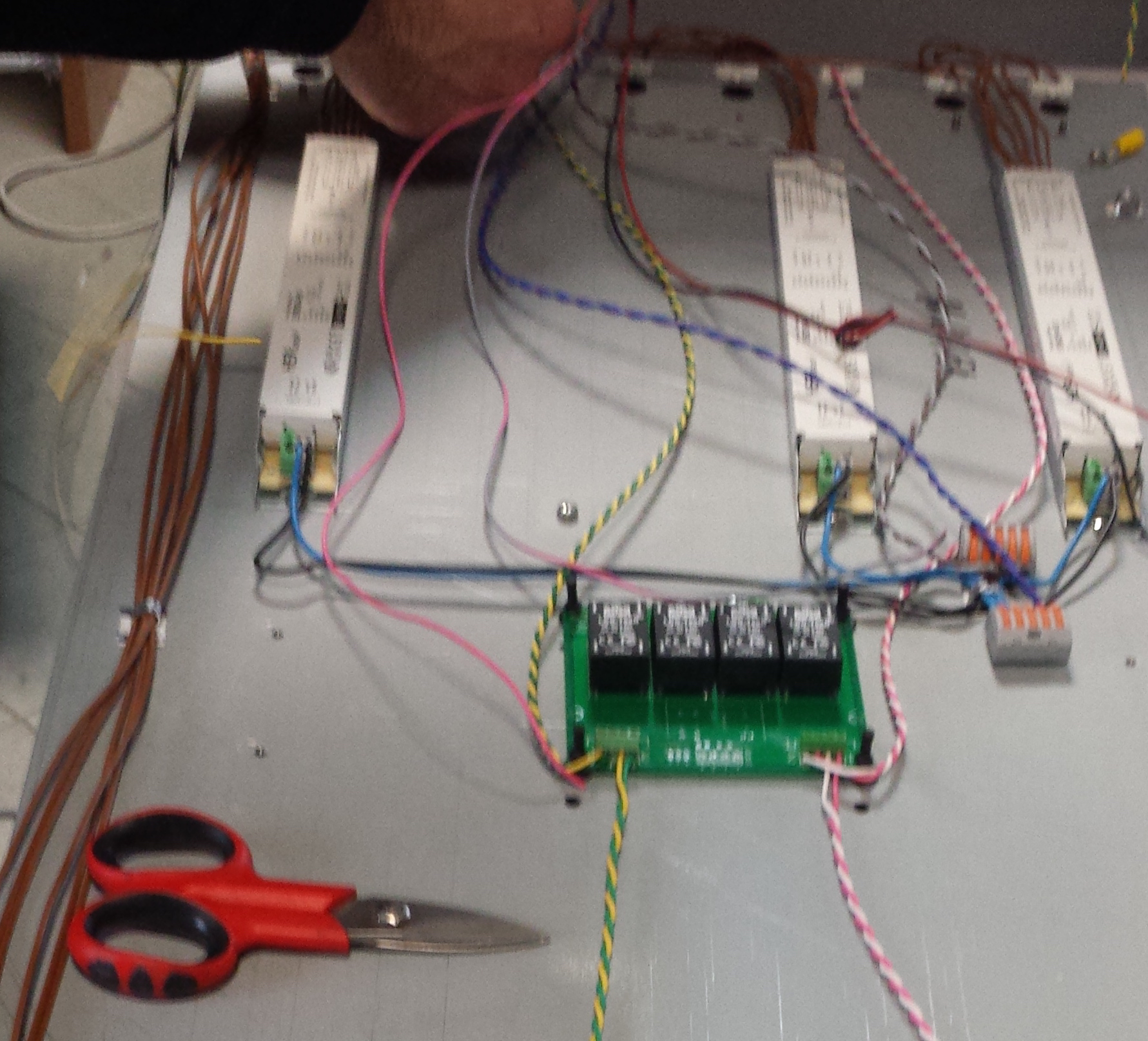
After having restored tube connections to ballasts check the operation, if everything works fine you can proceed to led installation. In the picture you can see 3 ballast operating the 6 remaining T5.
3- Start preparing the bars, cutting them to the right length, depending on original tube length. Remember to keep in account the length of connectors. For simplicity I report here the standard length of T5:
– 24 watt 549 mm
– 39 watt 849 mm
– 54 watt 1149 mm
– 80 watt 1449 mm
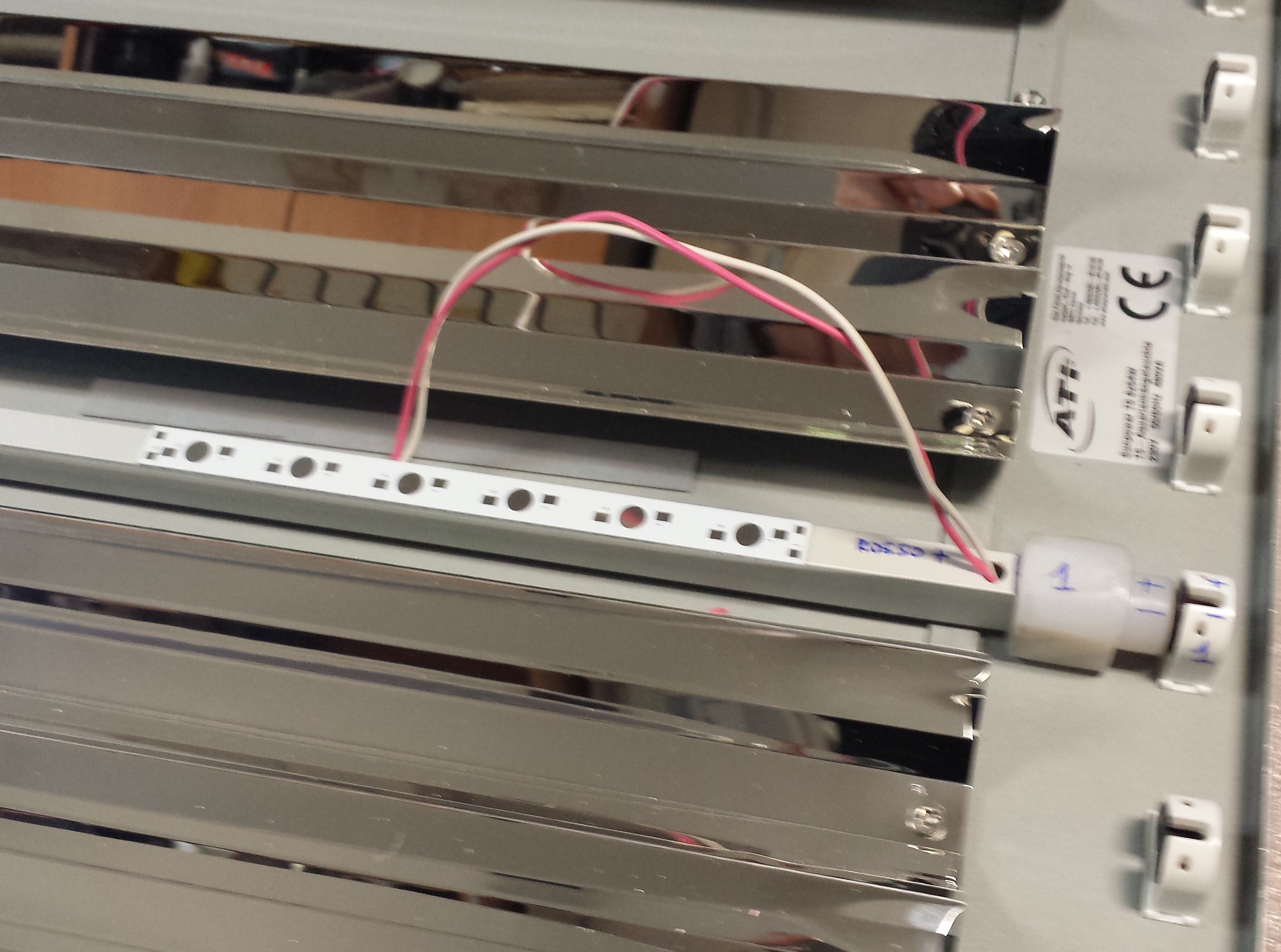
Now install the bars at the same way of tubes and check the correct orientation, keep in mind that the connector need a rotation of 90 degrees to hold in place and you risk to place leds facing tubes instead of water surface.
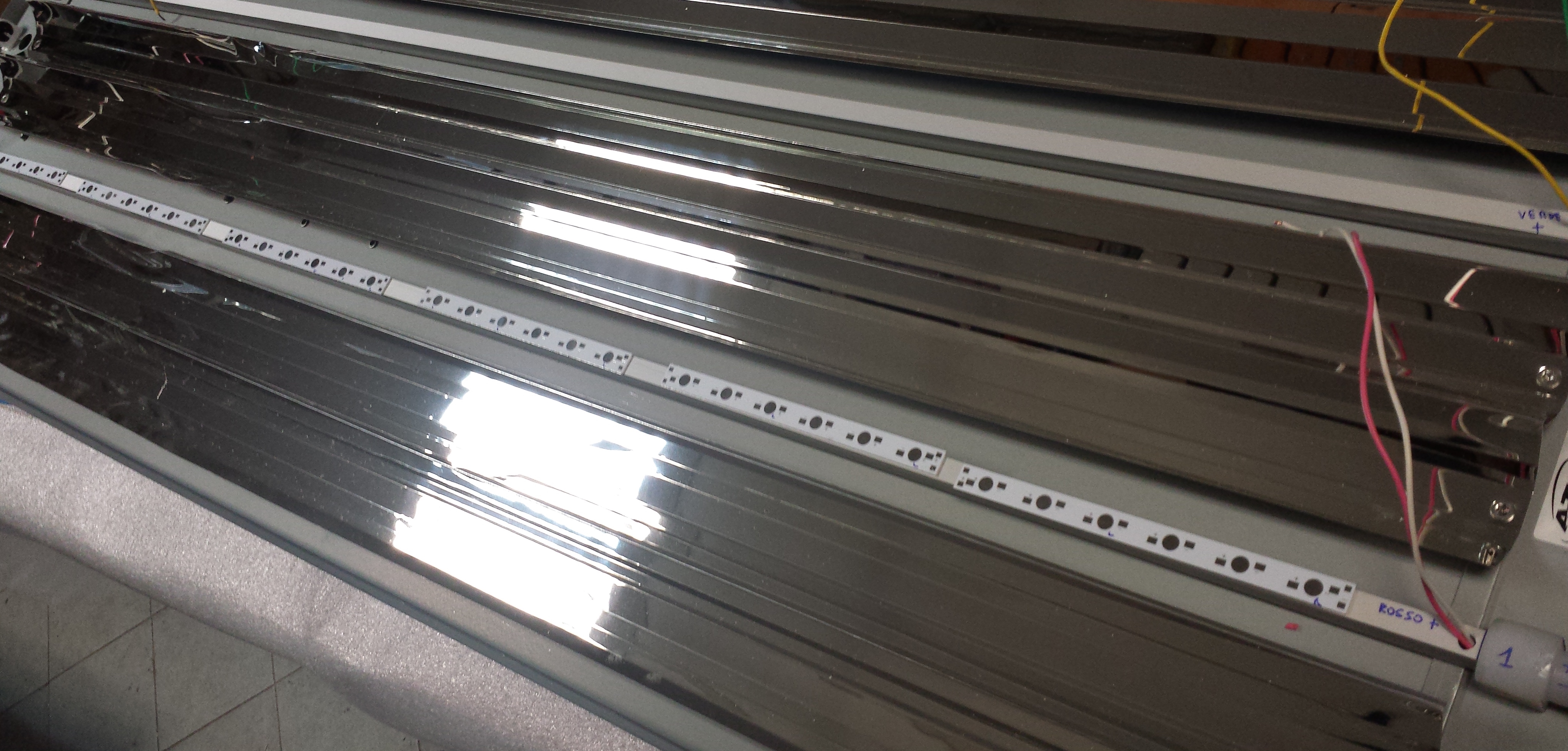
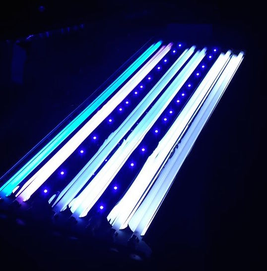
4- When bars are finished you can place and wire the leds with desired number and configuration, just keep in mind that such a bar can dissipate no more than 15 leds/meter with forced ventilation. If you want to mount more leds, get a better performing heatsink, compatible with the available space (remember T5 have a diameter of only 16 mm)
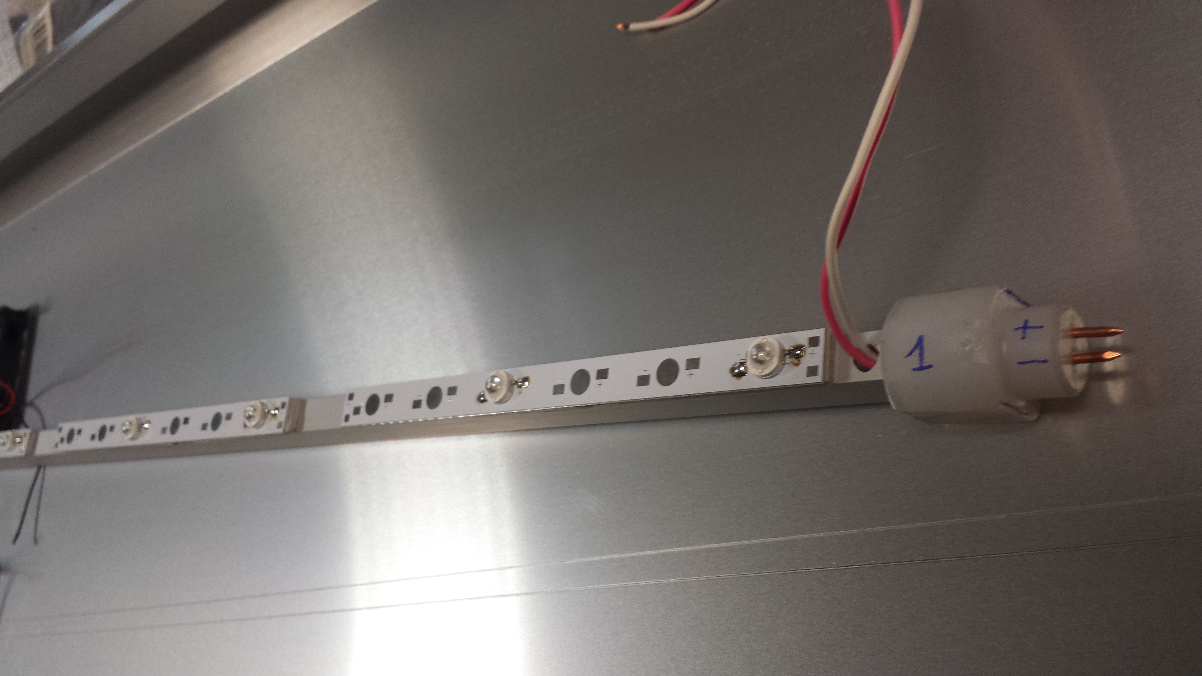
5- When bars are finished test them and, if working fine, finally install them. I suggest to mark polarity on both the bar and connector in order to avoid any possible inversion. It is also useful to cross-connect driver cables, so if you rotate the bar there is not polarity inversion and leds light up anyway.
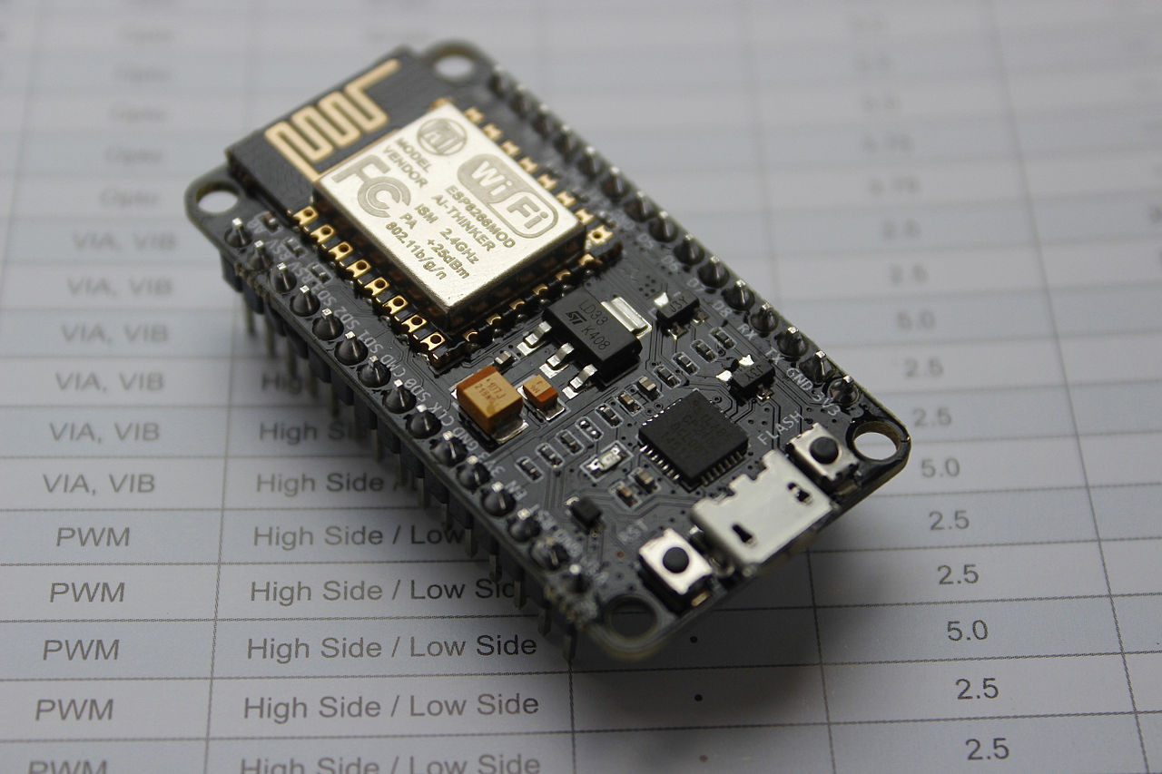
6- After having mounted bars, you can connect led drivers. For this project I used an external power source with internal constant current drivers (Meanwell ldd 700 mA), this arrangement reduces the total fixture weight.
7- When terminated wiring, check always is complete and test both leds and tubes. Proceed to reassemble the fixture and install it on your reef.